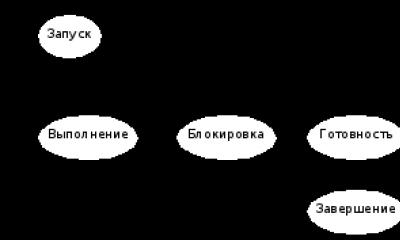
What is a crossover and why is it needed?Before answering this question, it is first necessary to take a short detour into loudspeaker theory and outline the problem. As is known, almost any speaker currently produced is capable of effectively reproducing only a narrow frequency band, limited from below by the resonant frequency of its moving system, and from above by the mechanical properties of the diffuser (weight, rigidity). Beyond this frequency band, the sound pressure created by the speaker decreases significantly and the level of distortion increases. We can't talk about high-quality sound. Therefore, to transmit the full spectrum of audio signals (20-20,000 Hz), it is necessary to use several speakers. Long ago, acousticians realized this need, and today in all areas of audio technology, be it home or automotive systems, the vast majority of speaker systems are implemented exclusively using a multi-driver design.
In relation to car audio systems, two fairly typical construction schemes can be distinguished, with which even more or less informed readers are familiar. The first and most common consists of three speakers: a subwoofer aimed exclusively at bass (approximately 20-100 Hz), a woofer/midrange speaker for the upper bass and mid-frequency ranges (100-3000 Hz), and a tweeter responsible for high frequencies (from 3000 Hz). Hz and higher). In more complex designs, such as those presented by professionals in car audio competitions, the number of speakers increases. Here, separate speakers are responsible for each frequency range: lower bass, mid/upper bass, mids and highs. But, despite the obvious differences, both schemes are subject to the same requirement: each speaker included in the speaker system must reproduce only its own frequency band and not affect neighboring ones. To fulfill this requirement, electrical filters are included in the audio path, which are responsible for highlighting some frequency bands and suppressing others. Obviously, if an acoustic system uses several speakers - a subwoofer, a bass/midrange driver, a midrange driver and a tweeter, there is a need to use several electrical filters. The combination of several such filters is called a crossover.
Filters
To a first approximation, any electrical filter is a combination of several elements that have the property of selectively transmitting signals of certain frequencies. The simplest circuits that have similar properties can be built using inductors and capacitors. The principle of operation of these circuits is based on the dependence of the resistance of the elements included in their composition on frequency: for inductors, the resistance increases with increasing frequency of the signal, and for capacitors, on the contrary, it decreases. Therefore, inductors pass low frequencies well, and capacitors pass high frequencies. These properties are used to construct filters - low-pass (LPF) and high-pass (HPF). In addition to low-pass filters and high-pass filters, there are other types of filters, for example, bandpass - in other words, bandpass. From the name it is clear that such filters pass only a certain frequency band well, and everything that is outside of it is suppressed by a bandpass filter (BF). The usual role of such filters is to isolate the mid-frequency range for subsequent feeding of the filtered signal to the midrange speaker. According to the task being performed, the next type of filter is a notch filter (RF) - the complete opposite of the PF. The band of frequencies that the PF passes through without changes is suppressed by the notch filter, opening free access to signals outside this frequency range. Somewhat different from all the above types of filters are infra-low frequency suppression filters (FINCH); in essence, these are the same high-pass filters, but with an extremely low cutoff frequency (10-30 Hz). The purpose of the FINCH is to protect the low-frequency head (subwoofer) from infra-low frequency signals, which can lead to overload of the subwoofer, and sometimes to its failure.
Each filter is characterized by several parameters. The first parameter of the filter is its order. The filter order corresponds to the number of reactive elements in the circuit (inductors, capacitors). A first order filter, as the name suggests, contains only one reactive element. A second-order filter contains two elements, etc. Another filter indicator is directly dependent on the order - the slope of the amplitude-frequency response. This parameter shows how sharply the filter attenuates signals outside the passband, that is, signals of those frequencies that should not overcome the filter barrier and reach the speaker. The slope is measured in decibels per octave (dB/oct). An octave is a frequency band in which the upper limit frequency is twice the lower frequency. For example, an octave can be considered frequency intervals from 100 to 200 Hz or from 200 to 400 Hz. It is easy to calculate that the entire range of sound signals (20-20,000 Hz) contains approximately ten octaves. The second unit of measurement is the decibel, named after the inventor of the telephone, A. G. Bell; this is the logarithm of the ratio of quantities (in this case, the filter's transmission coefficients at the cutoff frequencies of the octave), showing the relative difference between these quantities. A difference of 6 dB means that the levels differ by a factor of two, 12 dB by a factor of four, 20 dB by a factor of ten, etc. Now, returning to the slope of the amplitude-frequency response, we note that numerically it is directly proportional to the order filter and equals 6*N, where N is the order of the filter. Obviously, the slope of the first-order filter is 6 dB/oct, the second - 12 dB/oct, the third - 18 dB/oct, etc., and the higher it is, the more effectively the filters are able to suppress unnecessary signals. When choosing a filter order, along with the shape of the amplitude-frequency characteristic, it is necessary to take into account the phase-frequency characteristic. An ideally operating crossover should provide a uniform total frequency response in terms of sound pressure, which is summed up from the vibrations created by all heads of the speaker system. When summing, both amplitude and phase relationships appear, as well as the location of the heads in relation to the listener. The optimal result is ensured by using filters of a very specific order. Interested readers can find more detailed information on this matter, for example, in the book “Radio Broadcasting and Electroacoustics” edited by Yu. A. Kovalgin, published by the publishing house “Radio and Communications” in 1999.
At the same time, the filter function is characterized not only by the order and steepness of the frequency response decline. The approximation method on the basis of which its transfer function is determined can tell a lot about the nature of the filter. There are a lot of such methods today, and they all bear the names of their creators: Butterworth, Bessel, Linkwitz-Ralley and many others. It would seem that the large number of methods means many design differences in the implementations of filters even of the same order, but nothing like that. The reactive elements that can be seen on the electrical circuits of Butterworth, Bessel, Linkwitz-Ralley filters of the same order are the same, but the ratings of these elements are significantly different, which means different behavior of the amplitude and phase-frequency characteristics of the filters. As a result, the timing characteristics are also different.
In general, all types of filters are divided into two more fairly broad classes - active and passive, and, accordingly, the crossovers that include these filters can be passive and active.
Passive crossovers consist solely of reactive elements - inductors and capacitors, and do not require power. They are very undemanding, and under certain conditions they can be included in any part of the path, both before and after the power amplifier. But most often, passive crossovers are allocated a strictly defined area - between the power amplifier and the speakers. Using a crossover, it is possible to connect several heads operating in adjacent frequency bands to one amplifier. Cheap and cheerful! But there are also shadow sides. The presence of a crossover on the path between the power amplifier and the loudspeaker leads to the fact that up to ten percent of the useful energy is dissipated on the reactive elements and matching resistors. However, this is far from the only drawback of passive crossovers. We should also not forget that they have very limited capabilities for adjusting the sound, most often limited to level controls for individual frequency bands. The characteristics of passive filters depend significantly on the load resistance, which is the electrical resistance of the loudspeaker. In the operating frequency range it is very unstable, therefore optimal matching conditions cannot be ensured, and the frequency response of the filters differs from the calculated one. This also cannot be attributed to the advantages of passive crossovers.
Active crossovers in the service of automotive power amplifiers
If all the filter circuits currently used in audio equipment were built on passive elements, then most likely, over time, the copper reserves on planet Earth would be under threat. Why? Yes, because the manufacture of even the simplest first-order low-pass filter with a low cutoff frequency (100 Hz) based on an inductor requires a lot of copper wire, and not just a simple one, but the most serious one: a large cross-section, with low losses and high quality. It is unknown what we would be faced with today if several decades ago electronics specialists had not invented active filters, where bulky inductors and capacitors were replaced by electronic elements - transistors and operational amplifiers, which, when turned on in a certain way, in combination with resistors and capacitors have the same properties as LC circuits - identical phase shift between current and voltage and dependence of the transmission coefficient on frequency.
The appearance of fundamentally new filter circuits, like any other innovation in audio technology, immediately caused a lot of controversy. The main wave of criticism arose from the ranks of real audiophiles, who unanimously argued that active filters that require supply voltage are a serious obstacle to natural, natural sound. In this they were partly right, but the wide list of advantages of the newly introduced filters became a powerful argument in their favor. And soon these filters began to be actively used in built-in crossovers of car amplifiers. Such crossovers are usually located inside the amplifier housing, and their place in the signal path is at the input, immediately after the input sensitivity control circuits, before the pre-amplification circuits. It must be said that an important role in this transformation was played by the possibility of implementing active filters in minimalist dimensions, which remains a utopia for passive analogues to this day.
In budget amplifier models, built-in crossovers are based on identical filter units. This type of filter is a simplified variation of the Bessel filter; it is very simple to manufacture, because, unlike Linkwitz-Ralley, Bessel and Butterworth filters, it is built on elements of the same nominal value and is not particularly critical to tolerances for parameter deviations, which can sometimes reach many tens of percent. It is obvious that the amplitude and phase frequency characteristics of such filters are far from perfect, to say the least - they are the worst. The next pitfall that can be encountered in the design of budget-level built-in crossovers is related to the organization of the choice of crossover frequency. To reduce the cost of a crossover, many manufacturers deliberately minimize the number of tuning elements, and as a result, only one link of a second-order filter is tuned in frequency. It is clear that in this case it is quite difficult to talk about the stability of the crossover characteristics over the entire range of settings.
In amplifiers of the middle and high price categories, crossovers are most often implemented based on Linkwitz-Ralley, Butterworth and Bessel filters - second, third, and less often fourth order. Each of them has its own advantages and disadvantages, but, other things being equal, it is generally accepted that Butterworth filters have minimal frequency response unevenness, and Bessel filters have a phase response. In this class of amplifiers, to ensure precise adjustment of the cutoff frequency, many reputable manufacturers have adopted the so-called “click” method. Its essence is that the cutoff frequency of the high-pass filter and low-pass filter is adjusted according to a special “click-frequency” correspondence table, where, for example, the extreme left position of the potentiometer can correspond to a cutoff frequency of 20 Hz, the next - 22 Hz, etc., and the latter - five, and sometimes ten kilohertz. This tuning method is distinguished by very high accuracy of the result; it is found in amplifiers "PPI" and "Orion", etc.
A slightly different approach to setting the cutoff frequency is demonstrated by amplifiers produced by the Italian companies "Steg", "Audiosystem", as well as a number of other companies. Here, the desired cutoff frequency is selected by installing one or another resistive module-chip. This method is less universal than the one described above, however, it promises good results. A logical continuation of this approach are crossovers, in which the cutoff frequency is limited to a few fixed values. This is a fairly common solution, often found in high-end amplifiers. A good example is the many high end amplifiers from McIntosh. Here, the cutoff frequency of both filters - the high-pass filter and the low-pass filter - is fixed, and is limited to two values - 80 and 120 Hz. By the way, using these amplifiers as an example, we can demonstrate the use of notch filters in built-in crossovers. In them, the notch filter is tuned to the average resonance frequency of the car interior (150 Hz) and, to some extent, allows you to correct a possible rise in the amplitude-frequency response.
A special group consists of crossovers, in which you can adjust not only the cutoff frequency of a particular filter, but in addition also the slope of the amplitude-frequency response. Such broad capabilities are in themselves a rarity, but the Japanese “hDimension” amplifiers from the “Forte” series can boast of them, in which the maximum possible value of the slope of the attenuation characteristic reaches 48 dB/oct.
Sometimes in the low-frequency section of built-in crossovers you can find a high-pass filter with an adjustable quality factor, which allows you to increase the frequency response near the cutoff frequency up to 10 dB (Hawkins circuit). This circuit design is often found in Soundstream amplifiers; it allows you to exclude a separate stage of the bass boost circuit from the settings path.
The implementation of infra-low frequency suppression filters in built-in crossovers clearly demonstrates the advantages of active filtering. Such a filter on the board of many amplifiers takes up an insignificant area, but at the same time allows you to adjust the cutoff frequency in the range from 15 to 50 Hz, and with a slope of the attenuation characteristic from 18 to 24 dB/oct. True, some manufacturers sometimes deliberately reduce customization options, limiting themselves to a few fixed, typical values. As practice shows, this is more than enough.
Conclusion
After reading this review, many readers will probably want to ask a very reasonable question: is the use of a built-in crossover in car power amplifiers justified or is it just another way of withdrawing “hard-earned” funds? In many ways, the answer to this question depends on the level of the amplifier. If the device belongs to the budget or entry-level class, then it would certainly be naive to hope that the built-in crossover will not make significant changes to the signal. It's another matter when the amplifier belongs to the middle, or even elite class. Here manufacturers are playing by different rules. The credibility of the company is at stake, and the use of poor separation filters, as well as other elements, can damage its prestige. It is quite obvious that in this case you can seriously think about using an amplifier crossover, especially since high-end amplifiers usually have very good capabilities. Naturally, such a solution will lead to the construction of an audio system based on the principle of multi-band amplification (bi-amping), which does not help save the budget, because at least four amplification channels will be needed.
Homemade crossover for acoustics
Homemade crossovers for acoustics are needed to separate the frequency ranges of the speakers. They equalize these same ranges according to sound volume.
Making a homemade crossover for acoustics is not so difficult if you know some secrets.
What is a crossover and what do you eat it with?
First, let’s find out why we need a crossover?
This is a special device designed to separate audio frequencies. Crossovers seem to remove unnecessary frequencies and filter them.
For example, there are speakers (see) like tweeters. If there were no crossovers, then all frequencies, their full package, along with low frequencies and midrange frequencies, would be supplied to the tweeters. It is clear that this will ultimately negatively affect the detail of the music.
HF speakers, such as tweeters, are not capable of reproducing low and medium sounds and the presence of unusual frequencies will become a dangerous problem in this case.
Types of crossovers
Crossovers are usually divided into active and passive, as well as single-way, two-way, etc.
Passive crossover, its pros and cons
So:
- A passive crossover filters the signal with its capacitors, resistors and coils. As a result of this, the first drawback of such crossovers is revealed - loss of power.
- Passive crossovers are connected directly in front of the speakers. It turns out that it is enough to use just one amplifier (see), which is an undoubted advantage of passive crossovers.
- Passive crossovers are sold individually or as a set with speakers, usually two-way or more.
- Among the disadvantages of passive crossovers, one can highlight the limited peak load, which entails rapid failure.
Active crossover, its pros and cons
So:
- An active crossover is used in front of the amplifier. Therefore, using one amplifier in this case is simply impossible.
In the case of an active crossover, each speaker, be it a tweeter or a woofer, uses a separate amplifier channel.
- The advantage of an active crossover is that, unlike a passive one, it allows you to fine-tune the cuts. It is this factor that largely determines the cost of such a crossover, which is more expensive than its opponent.
Single-way crossover
- Designed to cut the subwoofer channel (see).
Two-way crossover
- Designed for two-way acoustics consisting of a tweeter and midbass.
Three-way crossover
- Designed for three-way acoustics consisting of a tweeter, midrange speaker and midbass.
Homemade crossovers
It happens that having become the owner of an expensive car acoustics, the owner discovers that the kit does not include crossovers. It is clear that it will be impossible to do without them, since the HF speakers can simply burn out.
What to do? The answer is ridiculously simple - make them yourself.
Tools
First, let's arm ourselves with the necessary tools:
- A good and convenient soldering iron.
- A special device that measures inductance.
- Glue "Moment".
- Ferric chloride.
- Foil fiberglass laminate.
- Heat shrink tube.
- Silicone sealant.
Step by step instructions
We begin the manufacturing process.
So:
- First of all, you need to carefully study the technical characteristics of the purchased speakers. It is recommended to pay special attention to the low frequencies of the tweeters, as well as the level of characteristic sensitivity of the LF and HF speakers.
- Then you need to choose the right one electrical diagram, implying the connection of a crossover.
Note. According to experts, it is advisable to give preference to 2nd order filters, because in a cramped car interior there is a strong increase in the frequency response at medium-high frequencies.
- It must be remembered that high-frequency speakers, which are connected through a 1st order filter, strongly emphasize hiss, and low-frequency speakers over-emphasize bright sounds. As a result, when put together, you get a mess, in which there will be a lot of bright and hissing sound.
Note. At the same time, the wider the interior of the car, the more it will be possible to minimize these shortcomings.
Inductor
So:
- We wind the inductors for the speakers. Note that when doing this for a woofer, it is better to use copper wire with a diameter of 1 mm and insulated with a special varnish.
Advice. When making coils, it is recommended to use ferrite cores. This will make it possible to obtain smaller dimensions and weight, as well as reduce the consumption of expensive copper wire. In addition, it will also be possible to reduce the active resistance of the coil.
- It is recommended to monitor the resulting inductance using a unique measuring device.
Advice. When winding wire, it is highly advisable to make a turn and a turn, and then fix it with glue. This will make it possible to avoid problems that beginners often encounter.
Making a printed circuit board
So:
- It's time to draw the board on paper. This must be done based on the sizes of the resulting coils and resistors.
- We draw the board and transfer it to a sheet of special material.
Note. It would be a good idea to choose foil-coated fiberglass as such a material.
- We immediately drill holes for the electrodes of future parts and wires. Be sure to etch the board. This must be done as follows: place the semi-finished board in a ferric chloride solution.
Assembly
- We assemble the boards of our future crossover according to the installation diagram.
Note. We carefully glue the inductors and capacitors to the board. It is recommended to use a good glue such as Moment. Good fixation will allow the homemade separator to work flawlessly for a long time in conditions of vibration and shaking.
Connecting speaker wires
So:
- We connect the speaker wires using a regular soldering iron. When working, you need to be extremely careful and not confuse the outputs for the low-frequency and high-frequency speakers. You also need to pay attention to the polarity.
- Glue will come in handy here too. It is necessary to fill the wires that are soldered with “Moment”, which will again protect against vibrations and possible fractures.
Connection
So:
- We carry out a test connection and make sure that the signal is supplied to each speaker from the corresponding output of the homemade crossover.
- If necessary, you can also include a 4 ohm resistor in front of the RF filter.
Note. We remember that the sensitivity of tweeters is several decibels higher than the sensitivity of the speaker reproducing low frequencies - as a result, tweeters play louder than the woofer.
We wrap the crossover ready with our own hands with a heat-shrinkable tube, observing required sizes. Be sure to fill the edges with silicone to prevent moisture or dust from getting inside the crossover.
The presented instructions will help you make a homemade crossover for acoustics without any problems. During the operation, it is recommended to study additional photos and video materials.
As for the price of consumables, it depends on the number of coils and speaker outputs. The material that is used is also important.
For common man, which is far from building speakers for playing music, the word “speaker crossover” does not mean anything. There is a lot of information on this subject on the Internet, including informational articles, as well as videos.
What is a crossover
This “box” is an essential part of the speaker system. This is due to the fact that there are no speakers in the world that can accurately reproduce the full range of frequencies. Therefore, two, three or more speakers are used to build speakers. However, do not forget about the “pancakes”. This type of speaker consists of several parts, due to which it boasts a fairly smooth frequency response over the entire frequency range.
A crossover is designed to separate the incoming signal into different components and send them to different speakers of the speaker system. Thus, the tweeter plays only high frequencies, and the woofer plays mid and low frequencies. A crossover is also called a filter.
The following elements are considered its main components:
- capacitor;
- inductor.
Together, these electrical elements “cut off” unnecessary frequencies that are sent to the speakers. By the way, capacitors and coils have different prices. Thus, the more expensive these elements are, the better the speaker system will ultimately sound.
Filter order
The final result will depend on the number of electrical elements. Depending on the number of capacitors and inductors, the filter comes in different orders. If the crossover consists of one element, say a capacitor, then the filter will be of first order. To obtain a second-order filter, the number of elements must be twice as large. The quality of filtering of unnecessary frequencies depends on the order of the crossover. This parameter is called slope and is measured in DB per OCTAVE. The higher the order of the filter, the higher the slope.

Active and passive
Crossovers are divided into two groups:
- active;
- passive.
Each type has its own advantages and disadvantages.
Active ones consist not only of capacitors and coils, but also of transistors. Thanks to this, the dimensions of the device were reduced. It is difficult to find an active crossover made as a separate element. They are basically an integral part of a car audio amplifier.
Passive ones are much more common. The main advantage of this type of crossover is that there is no need for additional power, so they are easy to install.
In addition, passive and active filters are divided into 3 more subtypes:
- High-frequency, designed to pass a high-frequency signal, cutting off everything else. This subtype is intended for tweeters.
- Low-frequency ones, on the contrary, cut off the upper frequencies and pass the low-frequency signal through themselves. Used for woofers.
- Wideband filter, also called Band Pass. This subtype is necessary to cut off frequencies outside a certain range. It is intended for midrange speakers.
Reading time: 3 minutes. Views 4.1k.
A crossover is a device designed to divide the input from the radio into sound signal into separate lanes. This device is used not only with full-range speakers, but also with special ones - subwoofers, midwoofers and tweeters. You should understand why a crossover is needed in car audio to achieve better and more natural sound.
Species
These devices for car acoustics are divided into two types: active and passive. In the first case, the accessory is equipped with an amplifier. This allows for more efficient audio stripping and adds the ability to adjust the crossover frequency, sensitivity and slope. Active separators are rarely produced as independent devices, most often being part of power amplifiers for car audio.
Passive crossovers are the simplest and most common. Such a device consists of several filters, which include coils and capacitors. The former delay high frequencies, the latter suppress low frequencies. To improve efficiency, coils and capacitors are combined into circuits. A passive splitter has one input and two or three outputs. Each speaker is connected to its own terminals. The radio is connected directly to the input of the separating device.
Based on the number of bands divided, crossovers are divided into two-way and three-way. In the first case, the device separates low and high frequencies, which are fed to the woofer and tweeter, respectively. Three-band devices also additionally highlight the mid-frequency band. It is fed to special speakers called midwoofers. One of the important advantages of a passive separator is that it does not require additional power. It is possible to adjust the sound characteristics using switches.
Connection instructions
A passive crossover for car audio is connected as follows:
- Speakers are purchased and installed.
- The output wires for the speakers from the radio are connected to the input terminals of the device.
- The speakers are connected using speaker cables to the corresponding terminals of the device, which may be designated Wf (for a full-range speaker), Sw (for a subwoofer), Mw (for a midwoofer) and Tw (for a tweeter).
For an experienced person, installing a speaker system is a simple task. But for a beginner, everything is difficult here. To properly install acoustics, you need to know what elements are needed and why they are needed. One such element is a crossover for acoustics.
Functional focus
A crossover is equipment that is an element of the speaker system. The main role is to distribute the required frequency range for the installed speaker. The acoustics are manufactured only for the specified frequency range. Therefore, if the signal is transmitted to speakers outside this range, the sound will be distorted.
For example, if you transmit a low frequency to the receiver, the sound will be distorted. If the frequency is very high, then this threatens with distorted sound and broken equipment, because it is not able to withstand such a level.
To perform high-frequency sounds, speakers are used that can transmit them. Speaker systems transmitting low frequencies operate separately. It is better if these speakers are placed separately from each other in the car. Mid-frequency sounds are sent to mid-range speakers.
Music will sound high quality when the sound is transmitted strictly to a specific speaker. This job is done by a crossover for acoustics.
Design
It looks simple, consists of 2 filters working according to the scheme. If the distribution frequency is 1000 Hz, then one of the filters will begin to select frequencies less than this value. The other, on the contrary, distributes them over 1000 Hz. The names of these filters are as follows:
- Low pass. Operates at low rates (up to 1000 Hz).
- High pass. Operates with high performance (more than 1000 Hz).
This is a diagram of the functioning of a two-way crossover. There are three-way speakers on the acoustic market. They also have an additional filter that distributes the frequencies of the average value (range 600-1000 Hz).
The higher the number of sound frequency distributions and their transmission to speakers for a specific purpose, the better the sound in the car.
Characteristic
The crossover consists of an inductor and a capacitor. The cost of the product depends on the number of parts and their properties. It is these simple elements that can easily process waves of different frequencies.

The capacitor selects and separates high-frequency sounds, and the inductor is directed to act with low frequencies. This is a simple but effective design.
Equipment options
There are 2 types of crossover.
- Passive equipment. This option is used most often. This element does not require separate power to operate. Because of this, installation of the system is faster and easier. But the quality does not always remain at a good level. During operation, the crossover takes part of the energy to work, which causes a phase shift. These changes may affect the operation of all equipment.
- Active. It has a complex design, but at the same time audio frequencies are filtered better than in a passive one. The device consists of several coils, capacitors and semiconductors. This design is often added to amplifiers.
Advantages and disadvantages
What is better to choose when installing acoustics? Let's consider the advantages and disadvantages.