Internal routing protocol RIP
This routing protocol is designed for relatively small and relatively homogeneous networks. The route is characterized by a vector of distance to the destination. Each router is assumed to be the starting point of multiple routes to the networks it is associated with. Descriptions of these routes are stored in a special table called a route table. The RIP routing table contains an entry for each machine being served (for each route). The entry must include:
- Destination IP address.
- Route metric (from 1 to 15; number of steps to destination).
- IP address of the closest router (gateway) on the way to the destination.
- Route timers.
Periodically (every 30 seconds), each router broadcasts a copy of its routing table to all neighboring routers with which it is directly connected. The destination router looks up the table. If there is a new path in the table or a message about a shorter route, or there are changes in path lengths, these changes are recorded by the recipient in its routing table. The RIP protocol must be able to handle three types of errors:
Cyclic routes.
To suppress instabilities, the RIP should use a small value for the maximum possible number of steps (no more than 16).
Slow distribution of routing information across the network creates problems when the routing situation changes dynamically (the system does not keep up with the changes). A small metric limit improves convergence, but does not eliminate the problem.
OSPF Link State Protocol
The OSPF (Open Shortest Path Firs) protocol is an implementation of the link state algorithm (adopted in 1991) and has many features designed for use in large heterogeneous networks.
The OSPF protocol computes routes on IP networks while preserving other protocols for exchanging routing information.
Directly connected routers are called "neighbors". Each router stores information about what state it thinks its neighbor is in. The router relies on neighboring routers and forwards data packets to them only if it is confident that they are fully operational. To find out the state of connections, neighboring routers quite often exchange short HELLO messages.
To distribute link status information throughout the network, routers exchange other types of messages. These messages are called router links advertisement - an announcement about the router links (more precisely, about the state of the links). OSPF routers exchange not only their own, but also other people's connection advertisements, ultimately receiving information about the state of all connections in the network. This information forms a graph of network connections, which, of course, is the same for all routers on the network.
BGP protocol
The general scheme of how BGP works is as follows. BGP routers of neighboring systems that decide to exchange routing information establish connections with each other using the BGP protocol and become BGP neighbors (BGP peers).
Next, BGP uses an approach called path vector, which is a development of the distance vector approach. BGP neighbors send (announce, advertise) path vectors to each other. The path vector, unlike the distance vector, contains not just the network address and distance to it, but the network address and a list of attributes (path attributes) that describe various characteristics of the route from the sending router to the specified network. In the following, for brevity, we will call a set of data consisting of a network address and attributes of the path to this network a route to this network.
BGP Implementation
A pair of BGP neighbors establishes a connection with each other using the TCP protocol, port 179. Neighbors belonging to different ASs must be directly accessible to each other; for neighbors from the same AS there is no such restriction, since the internal routing protocol will ensure the availability of all necessary routes between nodes of one autonomous system.
The flow of information exchanged between BGP neighbors over TCP consists of a sequence of BGP messages. The maximum message length is 4096 octets, the minimum is 19. There are 4 types of messages.
TCP/IP data transfer protocol
The Internet, which is a network of networks and unites a huge number of different local, regional and corporate networks, operates and develops through the use of a single TCP/IP data transfer protocol. The term TCP/IP includes the name of two protocols:
- Transmission Control Protocol (TCP) - transport protocol;
- Internet Protocol (IP) is a routing protocol.
Routing protocol. The IP protocol ensures the transfer of information between computers on a network. Let's consider the operation of this protocol by analogy with the transfer of information using regular mail. In order for the letter to reach its intended destination, the address of the recipient (who the letter is to) and the address of the sender (from whom the letter is from) are indicated on the envelope.
Similarly, information transmitted over the network is “packed in an envelope” on which the IP addresses of the recipient’s and sender’s computers are “written”, for example “To: 198.78.213.185”, “From: 193.124.5.33”. The contents of the envelope in computer language are called IP packet and is a set of bytes.
In the process of forwarding regular letters, they are first delivered to the post office closest to the sender, and then transferred along the chain of post offices to the post office closest to the recipient. At intermediate post offices, letters are sorted, that is, it is determined to which next post office a particular letter should be sent.
IP packets on the way to the recipient computer also pass through numerous intermediate Internet servers on which the operation is performed routing. As a result of routing, IP packets are sent from one Internet server to another, gradually approaching the recipient computer.
Internet Protocol (IP) provides routing of IP packets, that is, delivery of information from the sending computer to the receiving computer.
Determining the route for information to pass through. The “geography” of the Internet differs significantly from the geography we are accustomed to. The speed of obtaining information does not depend on the distance of the Web server, but on the number of intermediate servers and the quality of communication lines (their bandwidth) through which information is transmitted from node to node.
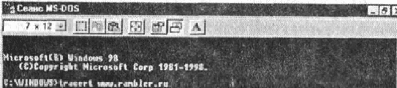
You can get acquainted with the route of information on the Internet quite simply. Special program tracert.exe, which is included with Windows, allows you to track through which servers and with what delay information is transferred from the selected Internet server to your computer.
Let's see how access to information is implemented in the "Moscow" part of the Internet to one of the most popular search servers on the Russian Internet www.rambler.ru.
Determining the route of information flow
2. In the window MS-DOS session in response to the system prompt to enter the command.
3. After some time, a trace of information transfer will appear, that is, a list of nodes through which information is transmitted to your computer, and the time of transmission between nodes.
 |
Tracing the route of information transmission shows that the server www.rambler.ru is located at a “distance” of 7 transitions from us, i.e. information is transmitted through six intermediate Internet servers (through the servers of the Moscow providers MTU-Inform and Demos). The speed of information transfer between nodes is quite high; one “transition” takes from 126 to 138 ms.
Transport protocol. Now let’s imagine that we need to send a multi-page manuscript by mail, but the post office does not accept parcels or packages. The idea is simple: if the manuscript does not fit into a regular postal envelope, it must be disassembled into sheets and sent in several envelopes. In this case, the sheets of the manuscript must be numbered so that the recipient knows in what sequence these sheets will then be combined.
A similar situation often happens on the Internet when computers exchange large files. If you send such a file as a whole, it can “clog” the communication channel for a long time, making it inaccessible for sending other messages.
To prevent this from happening, on the sending computer it is necessary to split the large file into small parts, number them and transport them in separate IP packets to the receiving computer. On the recipient computer you need to collect source file from individual parts in the correct sequence.
Transmission Control Protocol (TCP), that is, the transport protocol, ensures that files are split into IP packets during transmission and files are assembled during reception.
Interestingly, for the IP protocol responsible for routing, these packets are completely unrelated to each other. Therefore, the last IP packet may well overtake the first IP packet along the way. It may turn out that even the delivery routes for these packages will be completely different. However, TCP will wait for the first IP packet and assemble the source file in the correct sequence.
Determining the time of IP packet exchange. The time of exchange of IP packets between the local computer and the Internet server can be determined using the ping utility, which is part of the operating system. Windows systems. The utility sends four IP packets via specified address and shows the total transmission and reception time for each packet.
Determining the time of IP packet exchange
1. Connect to the Internet, enter the command [Programs-MS-DOS Session].
2. In the window MS-DOS session in response to the system prompt to enter the command.
3. In the window MS-DOS session The result of testing the signal in four attempts will be displayed. The response time characterizes the speed parameters of the entire chain of communication lines from the server to the local computer.
 |
Questions to Consider
1. What ensures the integral functioning of the global computer network Internet?
Practical tasks
4.5. Trace the route of information from one of the most popular Internet search servers www.yahoo.com, located in the “American” segment of the Internet.
4.6. Determine the time of exchange of IP packets with the www.yahoo.com server.
IP stands for Internet Protocol, and version 4 of this protocol is currently the most common. IPv4 is defined through RFC 791.
Within OSI, it is a network (3rd) layer protocol. This level, I remind you, is intended to determine the data transmission path.
IPv4 uses packet switching. In this case, the original transmitted message is divided into small parts (packets), which are transmitted independently over the network.
In addition, IPv4 does not guarantee packet delivery or the absence of duplicates. This is the so-called “best effort delivery” (as opposed to guaranteed delivery). Accordingly, these tasks are transferred to higher-level protocols, for example, TCP.
Addressing
IPv4 identifies the sender and recipient using a 32-bit address, which limits the number of possible addresses to 4,294,967,296. From this number, IPv4 reserves special address ranges called private (~18 million) and multicast (~270 million).
Addresses are usually written as four dotted decimal octets, for example: 198.51.100.25 corresponds to the number C6336419 16.
When using the global address space, it is necessary to distinguish between the addresses available in local physical network that does not require routing, and addresses that are physically located on another network. In the case of the latter, the packets are sent to the router, which must forward them further.
In the first versions of the standard, the first octet was used to identify the network, the rest - to identify the node. It quickly became clear that 256 networks was not enough. Therefore, classes of networks were introduced:
| Class | First bits | Network address length | Node address length |
|---|---|---|---|
| A | 0 | 8 | 24 |
| B | 10 | 16 | 16 |
| C | 110 | 24 | 8 |
| D | 1110 | N/A | N/A |
| E | 1111 | N/A | N/A |
| Class | Start of range | End of range |
|---|---|---|
| A | 0.0.0.0 | 127.255.255.255 |
| B | 128.0.0.0 | 191.255.255.255 |
| C | 192.0.0.0 | 223.255.255.255 |
| D | 224.0.0.0 | 239.255.255.255 |
| E | 240.0.0.0 | 255.255.255.255 |
Class D is reserved for multicast, class E is simply reserved “just in case”.
The length of the network address and the length of the node address were determined by the first bits of the address. Since about 1985, this has also been abandoned. The reasons for this are that many organizations required more addresses than the class C network provided and received a class B network. The class B network, however, exceeded the organization's requirements many times over.
Network classes have been replaced by network masks. This is a bitmask that specifies which bits of the address are network-specific and which are host-specific. By standard convention, the mask should be filled from left to right, so that the network address is always in the most significant bits. This allows you to specify only network address length, instead of the entire network mask.
For example, 192.0.2.0/24 means that the first 24 bits (three octets) are the network address and the rest are the host address. /24 is equivalent to the netmask 255.255.255.0.
The use of netmasks is described in RFC 1517.
Numerous standards also reserve different address ranges for special needs.
| Range | Description | RFC |
|---|---|---|
| 0.0.0.0/8 | Current network (source address) | 6890 |
| 10.0.0.0/8 | Private network | 1918 |
| 100.64.0.0/10 | CGN shared address space | 6598 |
| 127.0.0.0/8 | Loopback | 6890 |
| 169.254.0.0/16 | Autoconfiguration | 3927 |
| 172.16.0.0/12 | Private network | 1918 |
| 192.0.0.0/24 | IETF Protocol Assignments | 6890 |
| 192.0.2.0/24 | Documentation and examples 1 | 5737 |
| 192.88.99.0/24 | Relay ipv6 to ipv4 | 3068 |
| 192.168.0.0/16 | Private network | 1918 |
| 198.18.0.0/15 | Network Bandwidth Testing | 2544 |
| 198.51.100.0/24 | Documentation and examples 2 | 5737 |
| 203.0.113.0/24 | Documentation and examples 3 | 5737 |
| 224.0.0.0/4 | Multicast | 5771 |
| 240.0.0.0/4 | Reserved | 1700 |
| 255.255.255.255 | Broadcast Request | 919 |
Host addresses are also reserved, in binary representation consisting of zeros (indicates the entire network, reserved) and ones (broadcast request for a given network).
For example, 203.0.113.0 means (in the text) network 203.0.113.0/24, and 203.0.113.255 is a broadcast request to this network.
Package format
The packet consists of a header and data. IP does not involve any integrity checking. The underlying protocol (say, Ethernet) already provides integrity checking at the data link layer, and the higher-lying one (say, TCP) does so at the data layer.
Version, 4 bits First header field. In IPv4 it has the value 0010 2, i.e. 4. Header length, 4 bits The number of 32-bit words in the header. The minimum value is 5, which corresponds to a header length of 20 bytes. Maximum – 15, header length 60 bytes. DSCP or ToS – type of service, 6 bits Determines the prioritization, say, for VoIP. ECN, 2 bits Explicit network congestion flag. Requires support from both sides (receiving and transmitting). When this flag is received, the transmission speed is reduced. If the flag is not supported, the packets are simply discarded. Total Length, 16 bits The total length of the packet in bytes, including header and data. The minimum length is 20, the maximum is 65535. Identification, 16 bits Used to uniquely identify a datagram. Since it may be necessary to split a packet into smaller parts when transmitted over different networks, this field serves to identify the parts that belong to the same packet. Flags, 3 bits
Bit flags:
- Reserved, always 0
- Don't fragment. If further transmission of the packet requires fragmentation, the packet is discarded.
- More fragments. For fragmented packets, all but the last one have this flag set to 1.
- 1 - ICMP
- 6 - TCP
- 17 - UDP
Rarely used. Consists of header-data blocks. The option header is 8-16 bits long and consists of the following fields:
- Option type, 8 bits – a field that determines what kind of option it is. The value “0” means the end of the list of options. A total of 26 codes are registered.
- Length, 8 bits – the size of the entire option in bits, including the header. For some types of options may not be available.
ARP
IP defines logical addresses. However, in order to send a packet over an Ethernet network, you also need to know the physical address of the target node (or router). ARP is used to map one to the other.
ARP (Address Resolution Protocol) is formally a network (3rd) layer protocol in the OSI model, although in fact it ensures interaction between layers 2 and 3. ARP is implemented for various pairs of Layer 2 and Layer 3 protocols.
The protocol itself is built on a simple request-response scheme. Let's look at a specific example.
If host A, say, with logical address 198.51.100.1 (on network 198.51.100.0/24) wants to send a packet to host B, with logical address 198.51.100.2, it sends a Layer 2 protocol (in this case Ethernet) broadcast request with the encapsulated message An ARP asking network nodes what is the physical address of the node with the logical address 198.51.100.2, and containing the logical and physical addresses of node A. Node B, seeing its own logical address in the request, sends a response to node A at the logical and physical address received in the request. Query results are cached.
ARP messages have the following structure:
Physical protocol (HTYPE), 2 bytes Layer 2 protocol used. Ethernet has an ID of 1. Logical Protocol (PTYPE), 2 bytes Layer 3 protocol used. Corresponds to EtherTypes. IPv4 has an ID of 0x0800. Physical address length (HLEN), 1 byte Physical address length in octets, for Ethernet – 6 Logical address length (PLEN), 1 byte Logical address length in octets, for IPv4 – 4 Operation (OPER), 2 bytes 1 for request, 2 for an answer, and many other options for protocol extensions. Sender's physical address (SHA), HLEN byte In the request - the requester's address. The response contains the address of the requested node. Logical sender address (SPA), PLEN bytes
The recipient's physical address (THA), HLEN byte is ignored in the request. The response contains the address of the requester. Receiver logical address (TPA), PLEN byte
Typically, network hosts also send ARP messages when changing the IP address or when turning on. Typically this is implemented as an APR request where TPA=SPA and THA=0. Another option is an ARP response in which TPA=SPA and THA=SHA.
In addition, ARP can be used to detect a logical address conflict (with SPA=0).
There are protocol extensions that perform reverse operations, InARP (Inverse ARP), which receives an L3 address from an L2 address, and RARP, which obtains the L3 address of the requesting node.
RARP was used for auto-configuring L3 addresses. Subsequently replaced by BOOTP and then DHCP.
Routing in IPv4 networks
The basic routing algorithm in IPv4 networks is called the forwarding algorithm.
If there is a target address D and a network prefix N, then
- If N matches the network prefix of the current node, send the data over the local link.
- If there is a route for N in the routing table, send the data to the next-hop router.
- If there is a default route, send next-hop data to the default router
- Otherwise - an error.
The routing table is a table of mapping network addresses and next-hop router addresses for these networks. So, for example, a node with the address 198.51.100.54/24 may have the following routing table: 203.0.113.0/24
| Destination | Gateway | Device |
|---|---|---|
| 198.51.100.0/24 | 0.0.0.0 | eth0 |
| 203.0.113.0/24 | 198.51.100.1 | eth0 |
| 0.0.0.0/0 | 203.0.113.1 | eth0 |
Fundamentally, the route is also tied to the network device from which the data must be sent.
If a node can be reached via multiple routes, the route with the longer netmask (i.e., more specific) is selected. There can only be one default route.
For example, node 198.51.100.54/24 has a routing table:
| Destination | Gateway | Device |
|---|---|---|
| 198.51.100.0/24 | 0.0.0.0 | eth0 |
| 203.0.113.0/24 | 198.51.100.1 | eth0 |
| 203.0.113.224/27 | 198.51.100.5 | eth0 |
The global computer network Internet was initially built according to the following scheme: a backbone network, connected to it by networks called autonomous systems. The backbone network is also an autonomous system. This approach is convenient because detailed topological information remains within the autonomous system, and the autonomous system itself as a single whole for the rest of the Internet is represented by external gateways (routers through which autonomous systems join the backbone network). Internal gateways are used to form subnets within an autonomous system.
Accordingly, the routing protocols used on the Internet are divided into external and internal. External routing protocols (EGP, BGP) transfer routing information between autonomous systems. Internal routing protocols (RIP, OSPF, IS-IS) are used only within the autonomous system. Changing routing protocols and routes within an autonomous system does not affect the operation of other autonomous systems.
The OSPF (Open Shortest Path First) protocol was adopted in 1991. This is a modern protocol aimed at working in large heterogeneous networks with complex topologies including loops. It is based on a link state algorithm, which is highly resistant to changes in network topology.
40. Transport protocols of the TCP/IP stack.
Since connections are not established at the network layer, there is no guarantee that all packets will arrive at their destination unharmed or arrive in the same order in which they were sent. This task - ensuring reliable information communication between two end nodes - is solved by the main layer of the TCP/IP stack, also called transport.
The Transmission Control Protocol (TCP) and the User Datagram Protocol (UDP) operate at this layer. The TCP protocol provides reliable transmission of messages between remote application processes through the formation of logical connections. This protocol allows peers on the sending and receiving computers to communicate in full duplex mode. TCP allows you to deliver a byte stream generated on one computer without errors to any other computer included in the composite network. TCP divides the byte stream into segments and passes them on to the underlying internetworking layer. Once these segments are delivered by the internetworking layer to their destination, TCP reassembles them into a continuous stream of bytes.
UDP transports application packets in a datagram manner, like the main Internet Protocol (IP), and serves only as a multiplexer between the network protocol and multiple application services or user processes.
41. TCP/IP diagnostic utilities.
TCP/IP includes diagnostic utilities for checking stack configuration and testing network connectivity.
| Utility | Application |
| arp | Displays for viewing and editing the address translation table used by the Address Resolution Protocol (ARP - determines the local address from the IP address) |
| hostname | Displays the local host name. Used without parameters. |
| ipconfig | Displays values for the current TCP/IP stack configuration: IP address, subnet mask, default gateway address, WINS (Windows Internet Naming Service) and DNS (Domain Name System) addresses. |
| nbtstat | Displays statistics and current information on NetBIOS installed over TCP/IP. Used to check the status of current NetBIOS connections. |
| netstat | Displays statistics and current information on the TCP/IP connection. |
| nslookup | Checks records and domain aliases of hosts, domain services of hosts, as well as information operating system, by querying DNS servers. |
| ping | Verifies the correctness of TCP/IP configuration and verifies communication with a remote host. |
| route | Modifies IP routing tables. Displays table contents, adds and deletes IP routes. |
| tracert | Verifies the route to a remote computer by sending ICMP (Internet Control Message Protocol) echo packets. Displays the route of packets to a remote computer. |
To verify that TCP/IP is configured correctly, use the ipconfig utility. This command is useful on computers running DHCP (Dynamic Host Configuration Protocol) as it allows users to determine what TCP/IP network configuration and values have been set using DHCP.
The ipconfig utility allows you to find out whether the configuration is initialized and whether IP addresses are duplicated:
- if the configuration is initialized, then the IP address, mask, gateway appears;
- if IP addresses are duplicated, then the network mask will be 0.0.0.0;
- if, when using DHCP, the computer was unable to obtain an IP address, then it will be equal to 0.0.0.0.
The ping (Packet Internet Grouper) utility is used to verify TCP/IP configuration and diagnose connection errors. It determines the availability and functioning of a particular host. Using ping best way checking that a route exists between the local computer and the network host.
The ping command tests a connection to a remote host by sending ICMP echo packets to that host and listening for echo replies. Ping listens for each packet sent and prints the number of packets sent and received. Each received packet is checked against the transmitted message. If the connection between hosts is poor, the ping messages will tell you how many packets are lost.
By default, 4 echo packets of 32 bytes in length (a periodic sequence of uppercase alphabetic characters) are transmitted. Ping allows you to change the size and number of packets, specify whether to record the route it uses, what time-to-live (ttl) value to set, whether the packet can be fragmented, etc. When receiving a response, the time field indicates how long ( in milliseconds) the sent packet reaches the remote host and is returned back. Since the default value for waiting for a response is 1 second, all values in this field will be less than 1000 milliseconds. If you receive a "Request time out" message, it is possible that if you increase the response timeout, the packet will reach the remote host.
Ping can be used to test both a host name (DNS or NetBIOS) and its IP address. If a ping with an IP address succeeds, but a ping with a name fails, this means that the problem is in recognizing the match between the address and the name, and not in the network connection.
The ping utility is used in the following ways:
1) To verify that TCP/IP is installed and correctly configured on the local computer, the loopback address is specified in the ping command feedback(loopback address): ping 127.0.0.1
2) To ensure that the computer is correctly added to the network and the IP address is not duplicated, the IP address of the local computer is used:
ping localhost_ip-address
3) To verify that the default gateway is functioning and that a connection can be established with any local host in local network, the default gateway IP address is set:
ping gateway_ip-address
4) To check the possibility of establishing a connection through the router, the IP address of the remote host is specified in the ping command:
ping [options] IP address of remote host
Tracert is a route tracing utility. It uses the TTL (time-to-live) field of the IP packet and ICMP error messages to determine the route from one host to another.
The tracert utility can be more comprehensive and convenient than ping, especially in cases where the remote host is unreachable. Using it, you can determine the area of communication problems (at the Internet provider, in the core network, in the network of a remote host) by how far the route will be traced. If problems arise, the utility displays asterisks (*) or messages like “Destination net unreachable”, “Destination host unreachable”, “Request time out”, “Time Exeeded”.
The tracert utility works as follows: it sends 3 probe echo packets to each host through which the route to the remote host passes. The waiting time for a response to each packet is displayed on the screen (It can be changed using a special parameter). Packets are sent with different lifetime values. Each router encountered along the way reduces the TTL value by one before forwarding the packet. Thus, the lifetime is a counter of intermediate delivery points (hops). When a packet's TTL reaches zero, the router is expected to send an ICMP "Time Exeeded" message to the source computer. The route is determined by sending the first echo packet with TTL=1. The TTL is then incremented by 1 in each subsequent packet until the packet reaches the remote host or the maximum possible TTL value is reached (default 30, set with the -h option). The route is determined by examining the ICMP messages that are sent back by intermediate routers.
Syntax: tracert [options] target_host_name
The ARP utility is designed to work with the ARP cache. The main task of the ARP protocol is to translate IP addresses into corresponding local addresses. To do this, the ARP protocol uses information from the ARP table (ARP cache). If the required entry in the table is not found, then the ARP protocol sends a broadcast request to all computers on the local subnet, trying to find the owner of this IP address. The cache can contain two types of entries: static and dynamic. Static entries are entered manually and are stored in the cache permanently. Dynamic entries are placed in the cache as a result of broadcast requests. For them there is a concept of life time. If within a certain time (default 2 minutes) an entry has not been requested, it is removed from the cache.
The netstat utility allows you to obtain static information on some of the stack protocols (TCP, UDP, IP, ICMP), and also displays information about current network connections. It is especially useful on firewalls, and can be used to detect security breaches at the network perimeter.
Syntax:
netstat [-a] [-e] [-n] [-s] [-p protocol] [-r]
Parameters:
-a lists all network connections and listening ports of the local computer;
-e displays statistics for Ethernet interfaces (for example, the number of bytes received and sent);
-n displays information on all current connections (for example, TCP) for all network interfaces on the local computer. For each connection, information about the IP addresses of the local and remote interfaces is displayed along with the numbers of the ports used;
-s displays statistical information for the UDP, TCP, ICMP, IP protocols. The "/more" key allows you to view information page by page;
-r displays the contents of the routing table.